UK Aviation NavAids Gallery

It's true, I've risked losing all my friends by doing this project. I suppose it finally proves I am a geek at heart! (Is there a helpline I should ring?)

Seriously though - having spent many hours staring at dials and needles in an aircraft tracking many of these beacons, one builds a little semi-human relationship with them. I think this is called anthropormophism. Anyway, it seemed kinda cool to go visit them and build a gallery.

(Actually, my interest in transmitters seems to go way back to my childhood. I distinctly remember buying the IBA Yearbook and carrying it with me when we went on UK family holidays. I used to ask my Dad to divert so I could visit and photograph the TV masts.)

So.....like every good pilot should, I got the Long/Lats of the NavAids from the UK AIP at National Air Traffic Services. I then put them into streetmap.co.uk to get exact positions for each facility. Having printed a couple of map pages for each one - I keep the whole lot in the car. Every time I'm near a NavAid I've not yet been to - I'll photograph it and add it here. First one was 24th Feb '03. I'll keep going until I've done them all. (I'm mainly concentrating on the higher power Enroute facilities and not all the airfield ones.)

Actually, the project was a very relaxing thing to do while at flying school during the IR phase. I loved the mini-adventures of going to new places, the driving and the navigation exercises of trying to find the facilities! They're often in beautiful countryside and the surroundings can be quite picturesque. I also managed to see friends around the country at the same time.

There's definitely something very retro about the beacons both in physical design and of course the analogue technology employed. I guess they'll all be replaced by Digital Satellite Navigation in the end and my NavAids Gallery will just become a museum to the past!

If you're interested, I''ve put some explanations of the operation of VORs, DME & ADF/NDB below.

Trevor Diamond, Oxford, UK (td@trevord.com)

ps; Despite his protestations, I must give a special thanks to my Oxford Radio Nav lecturer - Stuart Dawson - who got me through the exam. His legendary Lancashire pronunciation of anything ending "ation" (think attenuation, modulation, navigation, integration, configuration......) will never be forgotten by us all.

Back to Trevor's Home Page

Enroute Navaids (AIP ENR listing)

BCN

BHD

BKY

BNN

BPK

BUR

CHT

CLN

CPT

DET

DTY

DVR

EPM

LAM

LIC

LND

LON

LYD

MAY

MID

HEN

HON

OCK

OTR

POL

SFD

STN

STU

TNT

WCO

WHI

WOD

Brecon

Berry Head

Barkway

Bovingdon

Brookmans Pk

Burnham

Chiltern

Clacton

Compton

Detling

Daventry

Dover

Epsom

Lambourne

Lichfield

Lands End

London

Lydd

Mayfield

Midhurst

Henton

Honiley

Ockham

Ottringham

Pole Hill

Seaford

Stornoway

Strumble

Trent

Westcott

Whitegate

Woodley

VOR / DME

VOR / DME

VOR / DME

VOR / DME

VOR / DME

NDB

NDB

VOR / DME

VOR / DME

VOR / DME

VOR / DME

VOR / DME

NDB

VOR / DME

NDB

VOR / DME

VOR / DME

VOR / DME

VOR / DME

VOR / DME

NDB

VOR / DME

VOR / DME

VOR / DME

VOR / DME

VOR / DME

VOR / DME

VOR / DME

VOR / DME

NDB

NDB

NDB

13th March 03

28th April 03

2nd March 03

3rd March 03

29th March 03

24th Feb 03

3rd March 03

4th May 03

25th Feb 03

15th March 03

26th March 03

15th March 03

10th March 03

27th March 03

26th March 03

28th April 03

1st March 03

15th March 03

10th April 03

10th April 03

12th March 03

2nd April 03

10th March 03

13th November 03

10th August 03

10th April 03

6th November 04

13th March 03

11th August 03

12th March 03

11th August 03

2nd March 03

On Airfield Navaids

GOW

OX

MCT

Glasgow

Oxford

Manchester

VOR / DME

NDB/DME/MKR

VOR / DME

1st June 03

25/2/03 & 26/4/03

10th Aug 03

VORs - Principle of Operation

When I was doing my JAA Radio Navigation exam I couldn't find much on the Net about VORs. I wanted to know a little more about their operation. I did some research and here's my summary of how they work.....

(Picture : Lambourne DVOR)

General Principle

VORs operate in the 108 - 118Mhz VHF range (just below the aircraft air-ground voice channels). They are low power 25-100W and provide 5 degrees navigation accuracy.

The general principal of VOR technology is to have two seperate 30Hz modulations on the VHF transmissions from the VOR station. The VOR is arranged such that one of the 30Hz signals remains in the same phase at all reception positions around the VOR (Reference signal). The other 30Hz signal received (Variable signal) will differ in phase by exactly the angular displacement of the receiver around the VOR from the Zero radial. The aircraft receiver demodulates the two 30Hz signals and simply compares their phase difference.

An audio ident in morse code at 1020Hz is also transmitted to enable pilot identification of the VOR tuned and verification of its servicibility. Some VORs have speech audio channels carrying ATIS or other ident info.

There are two main types of VORs in operation (ie two types of actual ground installation) but the aircraft receiver is the same for both. The receiver is unaware which type of ground station is in use - it experiences the same effects from both. It's the method of creation that differs.

Conventional VOR - CVOR

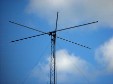
The CVOR employs a rotating directional antenna. Consider for a moment a directional antenna which has a transmission pattern of one broad peak and one broad null in the horizontal plane. If we were to feed this antenna with a VHF carrier and also rotate the antenna at 30 revs/second (1800RPM) - think of how an AM receiver would view this rotation. An AM receiver would see a carrier amplitude modulated by a sine wave of 30Hz - the phase of which would be determined by the receiver's position around the station.

A practical CVOR doesn't actually spin the aerial at 1800RPM (although the earliest ones did!) - it uses electronic switching of an aerial array to achieve the effect. Additionally, the reference signal is transmitted by FM modulating it onto a 9960Hz subcarrier (deviation +/-480Hz). The reference signal provides the receiver its comparison to station North. The receiver compares the AM 30Hz variable phase signal recovered with the decoded 30Hz reference signal from the FM subcarrier and determines the radial position from North on which the receiver lies.
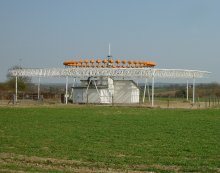
Doppler VOR - DVOR

The DVOR is a later and improved design of VOR which suffers less from siting errors. The CVOR requires a clear area of at least 1500ft in radius. The DVOR is more practical in crowded areas or where there are tall buildings. However, it's a big structure - around 100ft in diameter!

The DVOR reverses the useage of the two 30Hz signals. However, by also reversing the direction of it's rotating variable signal it produces exactly the same result in the receiver. The receiver has no "knowledge" that it's a DVOR as opposed to CVOR it's receiving and operates as normal.

In the DVOR the main VHF carrier is AM modulated at 30Hz - providing the Reference signal. This is transmitted from a central omnidirectional antenna and has the same phase all around the VOR for any receiver.

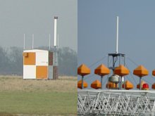
The effect of a 9960 FM modulated subcarrier is created using the Doppler effect by emplying a switched array of antenna arranged in a circle of diameter 44ft. (This distance being the exact amount to provide +/-480 apparent frequency shift in the subcarrier.)

Imagine a carrier of FcMHz AM modulated at 30Hz on the central antenna. Then imagine an array of an even number of aerial elements arranged around the cental aerial in a circle of diameter 44ft. (Typically 48 are used.) The VOR controller presents the subcarrier as sidebands on the opposite ends of an imaginary arm. Pairs of opposite aerials are switched in to form a rotating arm at 30Hz (1800RPM). The opposite aerials elements carry sidebands of (Fc+9960Hz) and (Fc-9960Hz).

From the receiver's perspective, there's a constant phase 30Hz AM modulation on the main FcMHz carrier but there also appears to be a 9960Hz subcarrier which is in turn frequency modulated at 30Hz. The sidebands will appear to be frequency modulated at 30Hz by +/-480 Hz due to the rotation and subsequent 44ft variation in distance between transmitting aerial and receiver causing Doppler Shift as the transmitting "arm" rotates. Of course, the phase of the 30Hz frequency modulation on the subcarrier (with respect to the reference signal) will depend on the receiver's angular position around the VOR. Hence, the same receiver comparison will result in the receiver's radial position being established as in the CVOR.

DME - Principle of Operation

Left - Oxford Airport stand-alone DME

Right - Colocated DME at LAM DVOR

General Principle

DME is a secondary radar system which determines slant distance between aircraft and ground station.

The airborne equipment simply measures the time that the radio signals take to travel from aircraft to ground station and back as the means to determine the range .

Detail

DME operates in the UHF band between 962 and 1213MHz. It employs 1Mhz spacing providing 252 channels. The aircraft is equipped with an Interrogator and the ground station is termed a Transponder.

As DME facilities are usually co-located with VORs or ILSs facilities and are used in conjuction with each other - the UHF DME channels are paired with VHF VOR & ILS frequencies. Operationally, the pilot has only to set the VOR/ILS frequency and the DME interrogator is tuned automatically to its correct channel pairing.

After selection, the aircraft's interrogator transmits a stream of pulse pairs and simulataneously starts a range-search. The ground based transponder receives the pulse train and re-transmits them after 50uS delay on a frequency which is +/-63MHz from the interrogation frequency.

The airborne interrogator identifies it's own stream of pulses and measures the time interval between the start of its interrogation and the response from the ground transponder. Accuracy is to +/- 0.2nm. The ground transponder can handle approximately 100 aircraft interrogators at once. (2700 pulse pairs per second)

The interrogation pulses are 3.5uS wide and are transmitted in pairs at 12uS (X-Channel) or 36uS (Y-Channel) intervals.The pulse pairs are transmitted by the interrogator at random intervals to differentiate themselves from the pulses of other aircraft. Pulse pairs are used to avoid the vunerability that would occur with a single pulse system - namely - misidentifying single pulses from lightening, other radar, ignition systems etc as valid.

As the ground transponder re-transmits all the pulses received from all aircraft the airborne interrogator sets up a "gate" to filter the received stream and allow through only it's own random pulse stream. As the distance between aircraft and transponder changes the interrogator adjusts it's gate to match. The DME interrogator is now said to have achieved lock-on and is in tracking mode.

NDB/ADF - Principle of Operation

Picture: Woodley NDB

General Principle

Automatic Direction Finding (ADF) simply provides the relative bearing of a basic ground based Non Directional Beacon (NDB) to the fore/aft axis of the aircraft by using a directional antenna assembly in the aircraft.

The NDBs are only basic AM transmitters which have been specifically sited and are continuously monitored for servicability. (There's no reason in principle why one couldn't use the ADF equipment to track to a known AM MW/LW broadcast mast.)

Detail

The NDB transmitter emits a vertically polarised AM modulated carrier in the LF or MF band. Allocated frequencies are 190KHz - 1750KHz. The carrier is modulated with an Audio ident in Morse Code.

Long range NDBs may have useful ranges of more than 50nm - possibly several hundred miles over oceanic areas. Low power Locator NDBs are often found on airfields and may only have a 10 - 25nm range. Accuracy is +/-5deg.

The basic principle of ADF systems is to use a directional loop aerial and a non-directional sense aerial to determine beacon position. Imagine a loop aerial placed in the plane of the transmitted radio wave. As the loop is rotated the current induced in it will vary. It will be maximum when it's in-line with the carrier and minimum when the loop is perpendicular to the carrier. As the loop continues to rotate beyond 180 degrees the current induced will be in the opposite sense. Hence, there will be two null positions where the loop is perpendicular to the transmission.

In order to eliminate one of the null positions (and so provide an unambiguous fix on the position of the beacon) an additional sense aerial is employed. The simple diapole sense aerial has a unidirectional (circular) polar diagram. By ensuring that the field from the sense aerial is in phase with one side of the loop aerial and then electronically adding the signals together - a resultant cardioid polar diagram of the whole assembly is established. The Cardioid now has one null when the loop aerial is rotated and can be used to establish the beacon's bearing.

A further detail remains. Because the null in the single cardioid pattern is not precise enough for ICAO navigational requirements the technique of rapidly reversing the polarity of the sense aerial is used. By switching the sense aerial at 120Hz a pair of cardioids is produced and a also more defined null.

Practical System

As an external airborne rotating loop antenna assembly is impractical, actual installed ADF systems use a fixed loop aerial assembly and Goniometer. The fixed loop assembly has four elements - two aligned with the aircraft fore/aft axis and two aligned perpendicular to fore/aft axis. The electrical fields induced in the elements are transmitted to a set of coils in the Goinometer - effectively recreating a local model of the fields experienced by the external loop elements inside the instrument. A further search coil detects the direction of the beacon and can drive a pointer.

Back to Trevor's Home Page